











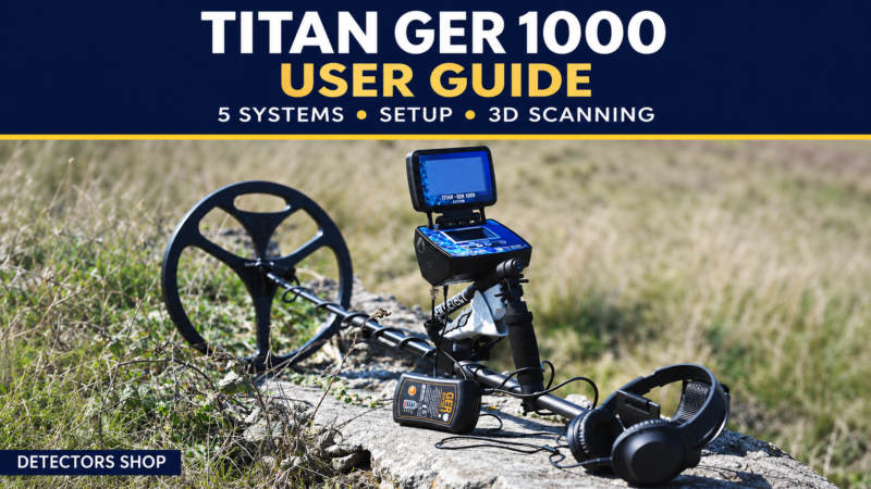
This Titan GER 1000 user guide explains how to assemble the detector, choose between its five systems, calibrate the search setup, connect the tablet and review results. It combines the supplied English manual, checks against the Arabic edition, manufacturer specifications and the photos and videos provided to Detectors Shop.
The most useful starting point is to separate the systems: a coil search, a magnetic indication and a coloured 3D scan do different jobs. Learning what each screen represents makes setup easier and helps you record findings more carefully.
Prepared by Detectors Shop. Operating references use PDF page numbers from the supplied 38-page English manual. Screens and menu names may differ with the tablet software and equipment version.
What Is the Titan GER 1000 Gold and Metal Detector?
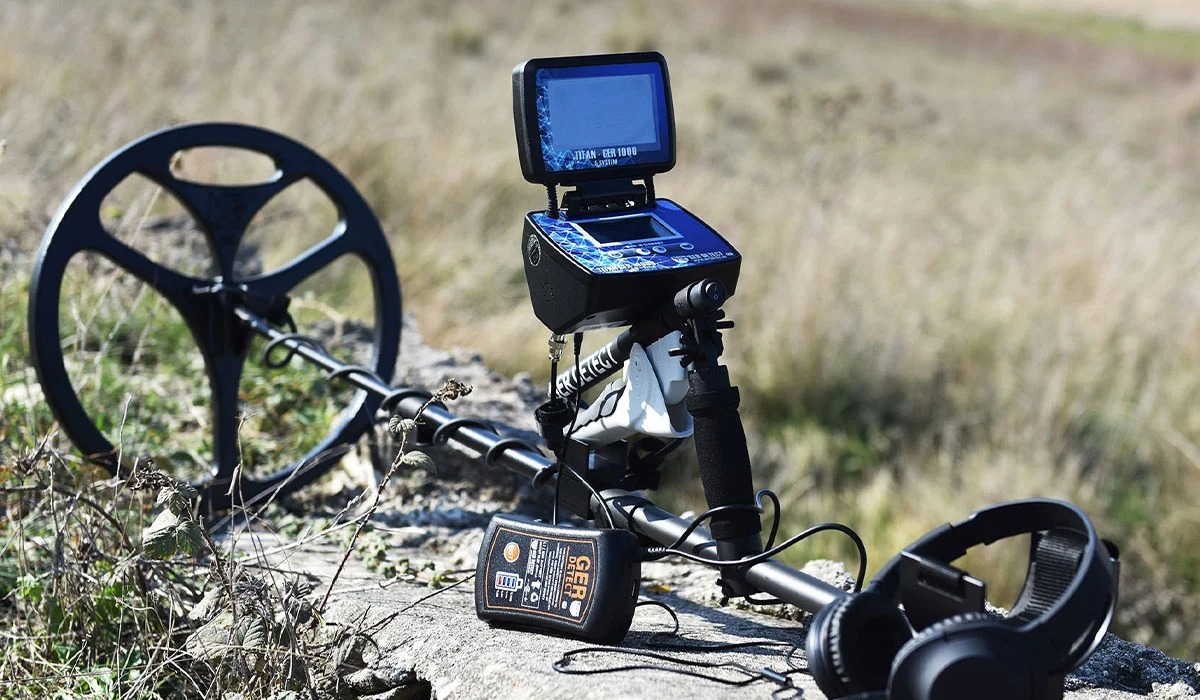
Titan GER 1000 is a GER Detect multi-system detector combining pulse induction, long-range sensing, an ionic mode, a magnetometer and 3D ground imaging. Different attachments and operating screens are used for the different functions.
The manufacturer markets it for buried metals and other underground search applications, including potential voids. Its target menus also include gold and gemstone categories. A selected target name is an operating setting; it does not establish the identity of an object beneath the ground.
This Titan GER 1000 user guide focuses on the operating sequence and how to check the information produced. It is a manual-based guide, rather than a report of a controlled detection-depth test.
| Question | Quick answer |
|---|---|
| How many main systems? | Five; cavity and gemstone options are not additional main systems. |
| Does it use a search coil? | Yes, for the pulse induction setup. |
| Where is the 3D view shown? | On the supplied tablet using the GER analysis software. |
| Bluetooth name and code? | GER3D; pairing code 1000 in the supplied manual. |
| Is every system rated to the same depth? | No. The English manual separately advertises 12 m for pulse induction. |
| Detectors Shop warranty? | Five years provided by Detectors Shop, subject to its written terms. |
Titan GER 1000 User Guide: Understanding the Five Search Systems
Choose the system before fitting its accessory. The five-system layout below follows the manual; it avoids counting a target category or a cavity mode as an extra independent system.
| System | Required setup | Information to review |
|---|---|---|
| Pulse induction (PI) | Coil, stem, control unit and battery | Audio response and the PI screen, including the available discrimination or cavity mode |
| Long range | Long-range assembly with transmitter and receiving antennas | Selected target category, range setting and direction indication |
| Ionic | Ionic sensor and main unit | Audio and on-screen indications after the manual’s calibration sequence |
| Magnetometer | Magnetic sensor and main unit | Magnetic-search indications; not chemical identification of gold |
| 3D imaging | Imaging sensor, tablet holder, tablet and Bluetooth connection | Recorded grid data, processed shapes, selected-cell information and depth estimates |
The manufacturer describes long-range and ionic functions as preliminary search methods. Treat their indications as candidates to recheck. Agreement between screens can guide further investigation, but does not independently prove target material, size or depth.
For background on detector terminology, read how gold and metal detectors work.
Parts, Accessories and Package Checklist
Detectors Shop confirms that its package includes the items described in the supplied manual. Before the first session, lay out the parts and identify which belong to each system. Keep the packing list with your invoice.
| Component group | What to identify and inspect |
|---|---|
| Main detector and controls | Power connection, display, controls and the correct attachment connection |
| PI coil assembly | Stem/handle, large and small coils, coil cable and securing points |
| Long-range parts | Long-range unit, transmitter, receiver and receiving antennas |
| Ionic attachment | Ionic sensor and its connector |
| Magnetic and imaging attachments | Sensor arrangement required for the selected system; match it to the manual diagrams |
| Tablet equipment | Tablet, holder and supplied analysis software |
| Power and audio | External rechargeable battery, original charger, relevant leads and supplied headphones |
| Transport and documentation | Protective case, user documentation and warranty paperwork |
Do not force a connector or substitute an attachment because it appears to fit. If the supplied kit differs from a diagram, send Detectors Shop a photograph of the part and connector before operating that system.
Titan GER 1000 Technical Specifications
These values follow the manufacturer’s published specifications. They describe the equipment; they do not establish detection performance.
| Specification | Published value |
|---|---|
| PI display | 128 × 64 px LCD |
| Other-system display | 480 × 270 px colour touchscreen; 98 × 57 mm |
| Frequency | PI: 350 Hz; other systems: maximum 500 kHz |
| Processing | PI: 20 MHz; other systems: 8 MHz |
| Coils | 45 cm and 20 cm diameters |
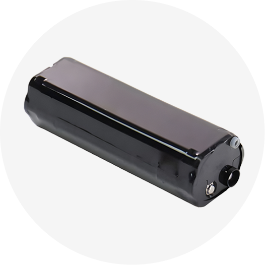
| External battery | Rechargeable Li-ion; 10.8 V; capacity listed as “54 Watt” |
| Advertised runtime | PI: 10 hours; other systems: 18 hours |
| Operating temperature | Detector: 0–70°C; battery: 0–50°C |
| Detector storage temperature | −20–70°C |
| Operating humidity | Up to 95%, non-condensing |
| Bluetooth | HC-05; 2.4 GHz |
| Water protection | Coil: listed to 30 cm; detector: not waterproof |
| Device / total weight | 550 g / 8600 g |
| Empty case | 4300 g; 670 × 500 × 270 mm |
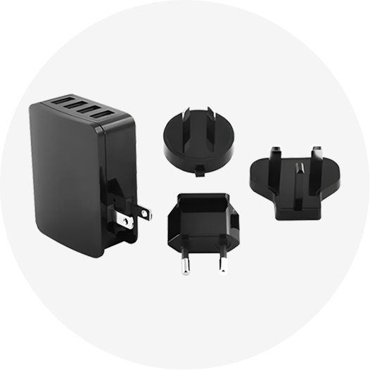
| Charger | Input: 90–250 VAC, 50–60 Hz; output: 12.6 VDC, 1000 mA |
The published battery label uses “Watt” without an energy unit. Check the battery label for its Wh/Ah rating. The listed 550 g is not the complete assembled kit weight. Runtime depends on condition and use.
Before You Start: Power, Site and Equipment Checks
Use this Titan GER 1000 user guide alongside the supplied manual during setup. The most important PI startup instruction is to connect the coil cable before switching on the PI unit; the manual warns that an unconnected coil can interrupt startup.
- Charge first. Use the supplied original charger and inspect the battery housing and leads.
- Choose a suitable practice area. Start away from vehicles, fences, obvious scrap and power infrastructure. Locate buried services before any recovery work.
- Reduce carried interference. The manual asks users to remove watches, jewellery and other carried metal, and keep phones and electronics away from the search setup.
- Check conditions. The manual advises against rain and extremely wet ground. Keep the electronics and connectors dry.
- Assemble the selected system. Check cable routing, locking points and battery connection before power-up.
- Identify the controls. Learn power, Start, calibration/Menu and navigation controls on your version before searching.
- Record a baseline. Note the system, attachment, settings, ground condition and any background response.
A stable response matters more than a high setting. If background noise makes individual indications difficult to repeat, review the setup and calibration before interpreting targets.
Titan GER 1000 User Guide: Pulse Induction Setup and Search
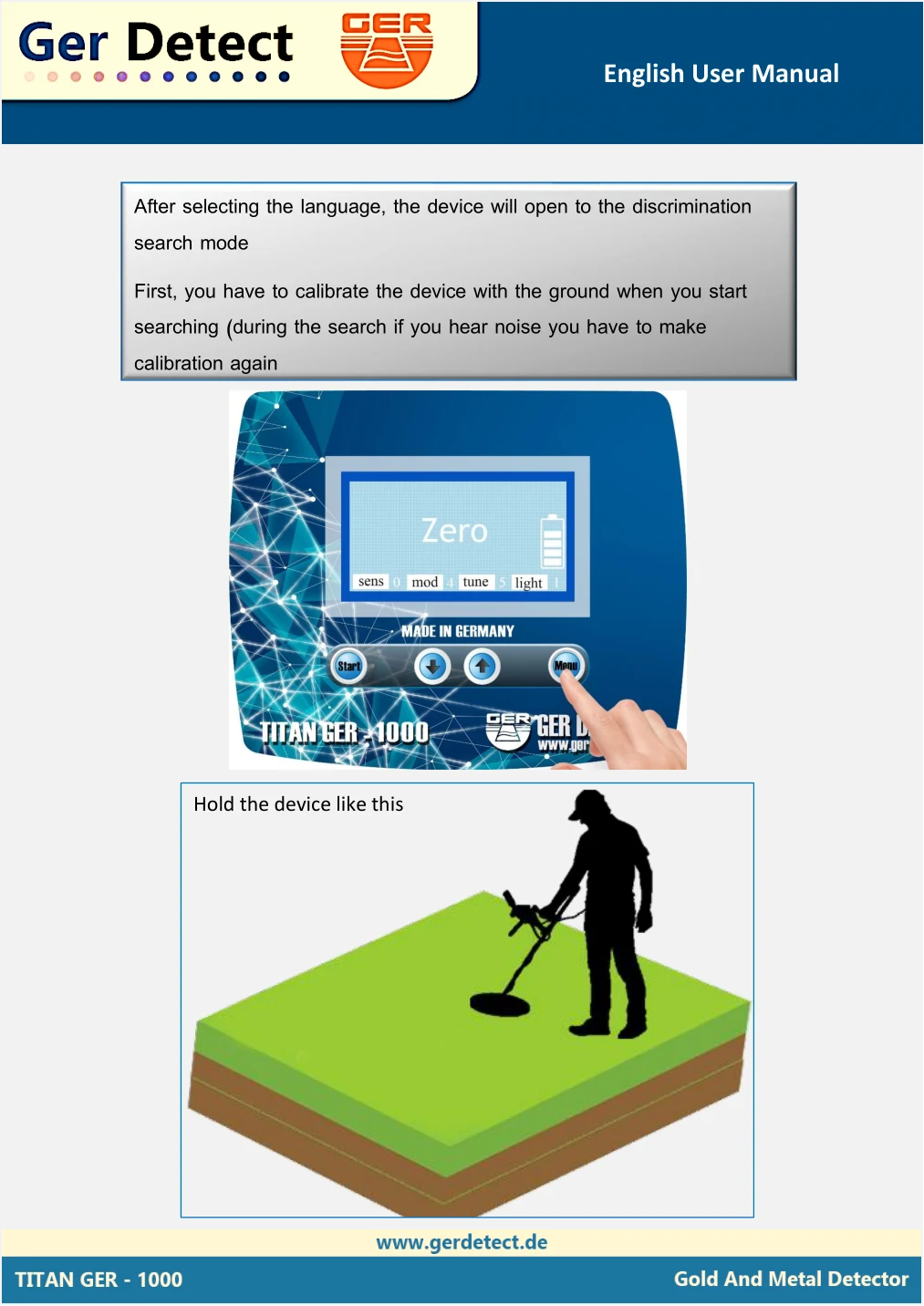
The PI setup is the coil-based part of the detector. The English manual covers it on PDF pages 32–37, including startup, ground calibration, sweeping and the displayed discrimination/cavity functions.
- Fit the selected coil and adjust the stem and armrest for a comfortable stance.
- Route and connect the coil cable, leaving enough freedom for adjustment without pulling on the connector.
- Connect the battery and switch on only after the coil connection is complete.
- Use Start and the navigation buttons to select the language as shown in the PI instructions.
- Perform the ground-calibration procedure illustrated in the manual. The calibration example shows a zero response.
- Begin with controlled left-to-right sweeps. The manual specifies a coil height of approximately 5–10 cm above the ground.
- Use the up/down controls for sensitivity as described. Recalibrate if ground-related noise develops.
- When a response repeats, recheck from another direction and record its location before deciding what to investigate.
Normal Search, Discrimination and Cavity Options
The Arabic manual separates normal search, discrimination and cavity search. The English edition groups the explanation differently and describes two modes. Use the controls and menu labels actually present on your equipment rather than assuming every version has identical wording.
A non-ferrous indication does not identify gold. Copper, aluminium, bronze, silver and gold are all non-ferrous materials. The English manual’s example list incorrectly groups copper and aluminium with ferrous metals; do not use that list as a metal-classification reference.
The manual also describes a cavity-search option. Treat the output as an indication requiring independent site assessment, rather than proof that a cavity exists or that a suspected void is safe to enter.
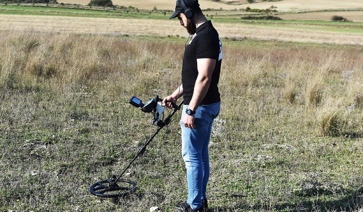
Long-Range System: Assembly, Target Menu and Range
This section of the Titan GER 1000 user guide follows English manual PDF pages 4–11. It describes the manufacturer-directed procedure; a direction indication is not an independently verified location or metal identification.
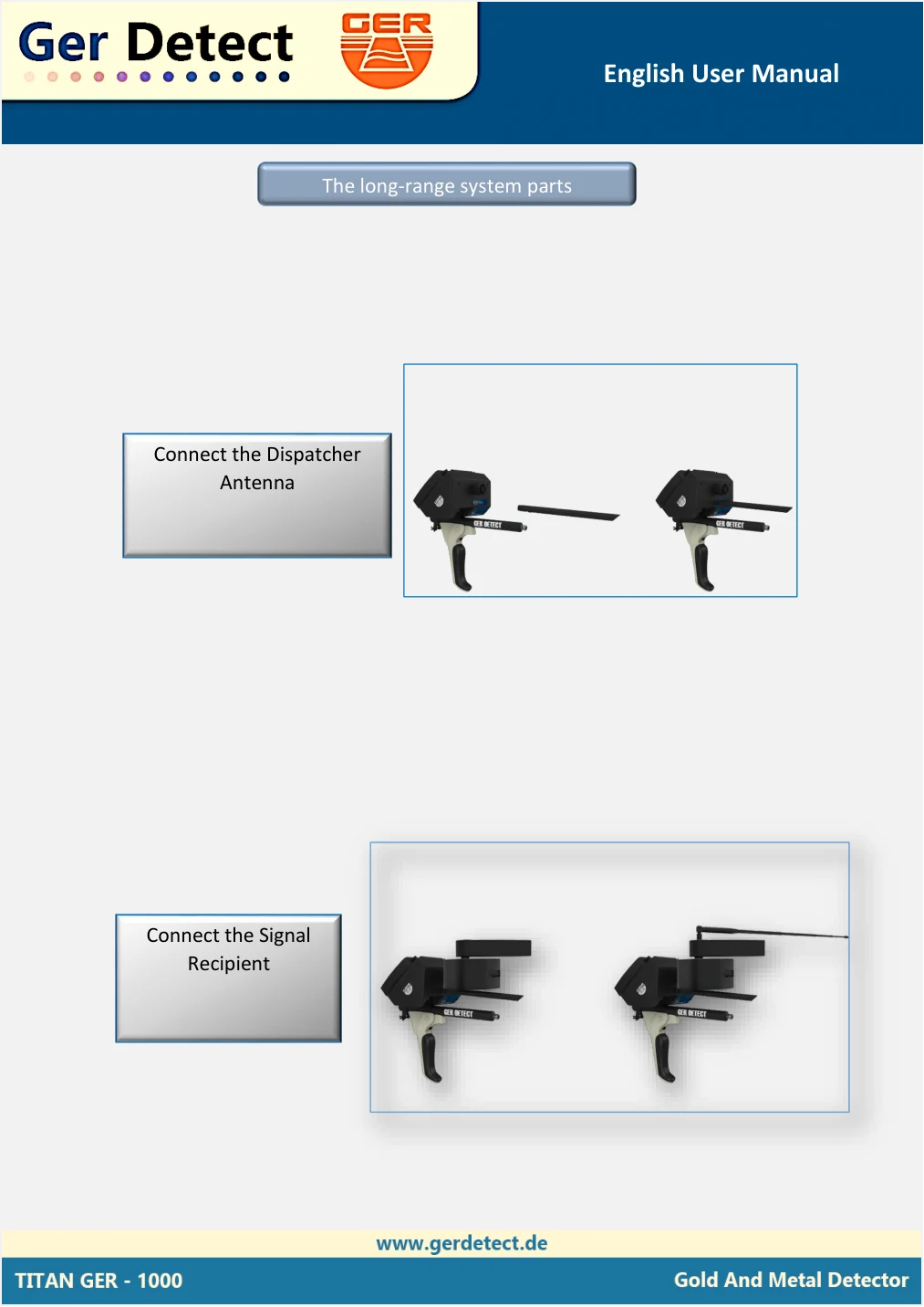
- Fit the transmitter assembly, signal receiver and receiving antennas according to the diagrams.
- Connect the battery, open the screen and switch on.
- Select the operating language, then the long-range system.
- Choose a target category from the menu. Keep that selection in your survey notes.
- Select the displayed range: 500, 1000, 1500, 2000 or 2500 m.
- Extend and orient the receiving antennas as instructed, matching the screen indicator to the forward direction.
- Follow the manual’s holding position and observe the direction response.
- Mark any candidate location and repeat the approach from north, south, east and west.
What Does the 45-Degree Depth Procedure Mean?
The manual describes standing at the indicated centre, turning 45 degrees, walking until the antenna reverses, and measuring the distance back to the centre. It equates that distance to target depth.
Record this as the manual’s antenna-based estimate. This guide has no independent validation establishing that the walked distance measures burial depth. Keep it separate from a software depth estimate and any actual measured recovery depth.
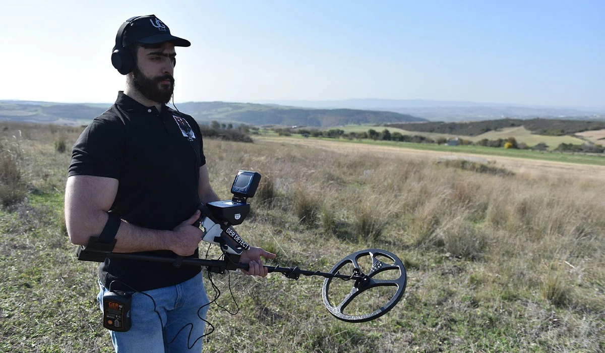
Ionic Search System: Connection and Calibration
The manufacturer describes this as a search mode associated with long-buried targets. The operating sequence below follows English manual PDF pages 12–17 without presenting the manufacturer’s explanation of “ionic fields” as independently demonstrated performance.
- Connect the ionic sensor before switching on.
- Connect the battery, open the screen and choose the language.
- Select the ionic system and follow the north/south orientation screen.
- Point the setup towards the ground. If a background sound occurs, use the calibration control shown in the manual.
- After calibration, move through the illustrated 180-degree right/left search arc.
- Observe audio and indicator changes, mark the area and repeat the procedure before further investigation.
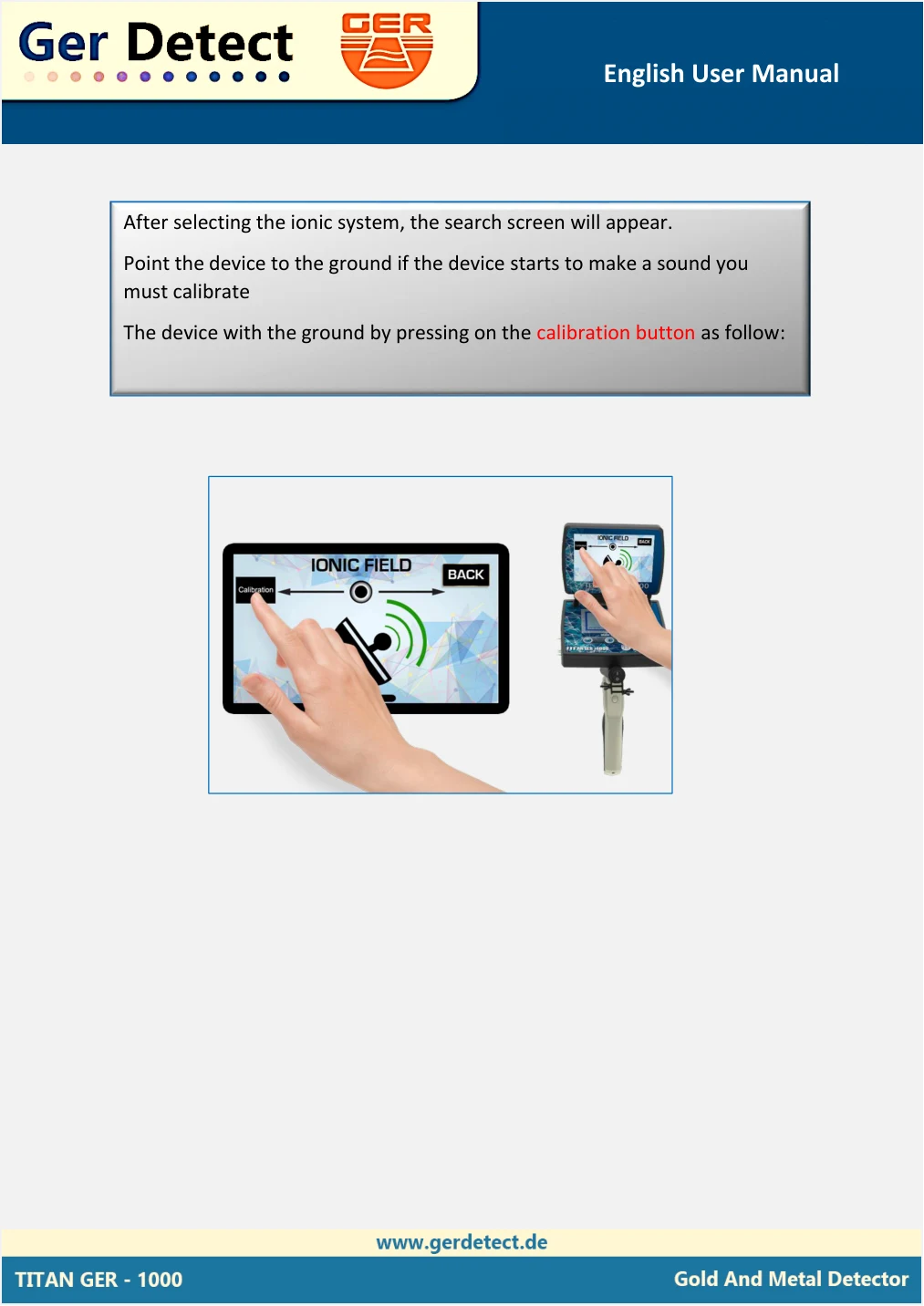
The manual warns that north-facing orientation can produce a response in this mode. Check orientation and calibration before interpreting a sound as a target. It also says surface or newly buried test objects do not represent its claimed ionic operation; that statement is not evidence that an indicated buried target exists.
Although the manual illustrates use from a moving vehicle, this guide recommends learning the procedure while stationary and on foot in a suitable area. Do not operate the detector while driving.
Magnetometer System: Magnetic Search and Repeat Checks
Magnetic searching serves a different purpose from coil discrimination. The manufacturer describes this system for magnetic metals such as iron. A magnetic indication alone is not a direct identification of gold.
- Connect the magnetic sensor in the arrangement illustrated in the manual.
- Power on, select the language and choose MAGNETOMETER.
- Complete any orientation step shown on your version. The Arabic edition includes a compass/Continue screen.
- Point towards the ground and use calibration if background sound is present.
- Search using the described forward/back movement, keeping sensor position consistent.
- Mark a repeatable response, move away, then rescan. Check nearby surface iron and carried metal before interpreting it.
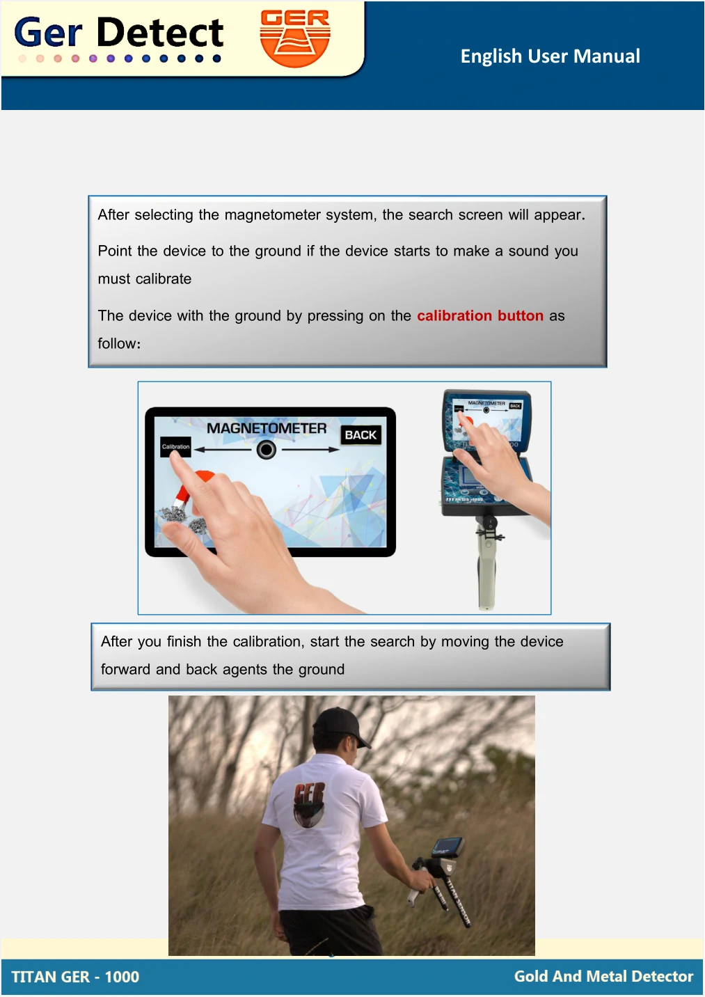
The English manual repeats a long-buried-target explanation under this system. Do not treat burial age as a general requirement for ferrous objects to have a magnetic response. Use controlled checks and record the observed response rather than inferring target age or value.
Titan GER 1000 User Guide: 3D Assembly and Bluetooth Pairing
The imaging setup records a scan grid for viewing in the tablet software. Fit the imaging sensor and tablet assembly before pairing. English manual PDF pages 18–27 cover this process.
Assemble the Imaging Configuration
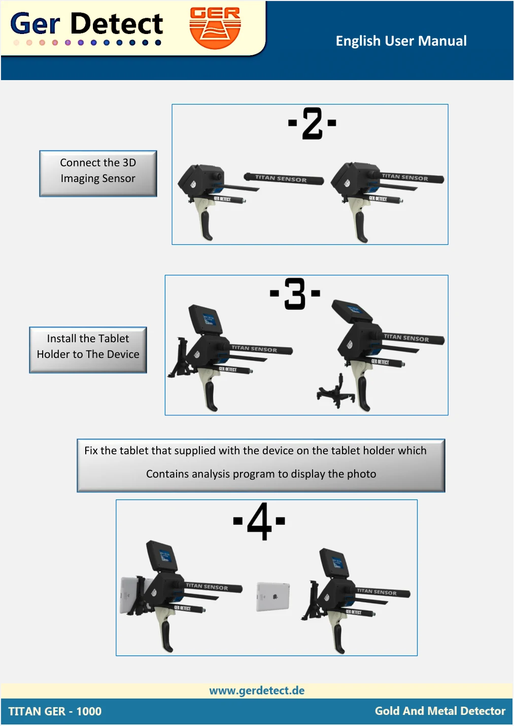
- Connect the transmitter antenna and imaging sensor as shown in the manual.
- Fit the tablet holder securely to the detector.
- Secure the supplied tablet so it cannot shift while you walk.
- Connect the battery and switch on the equipment.
Pair GER3D with the Tablet
- Open the tablet’s Bluetooth settings and search for nearby devices.
- Select GER3D when it appears.
- Enter 1000 when the pairing code is requested and confirm.
- Open the supplied GER imaging application and choose 3D IMAGING on the detector.
- If your software requires a COM port, use the port assigned to the paired device. The Arabic manual’s COM17 is an example, not a fixed port for every tablet.
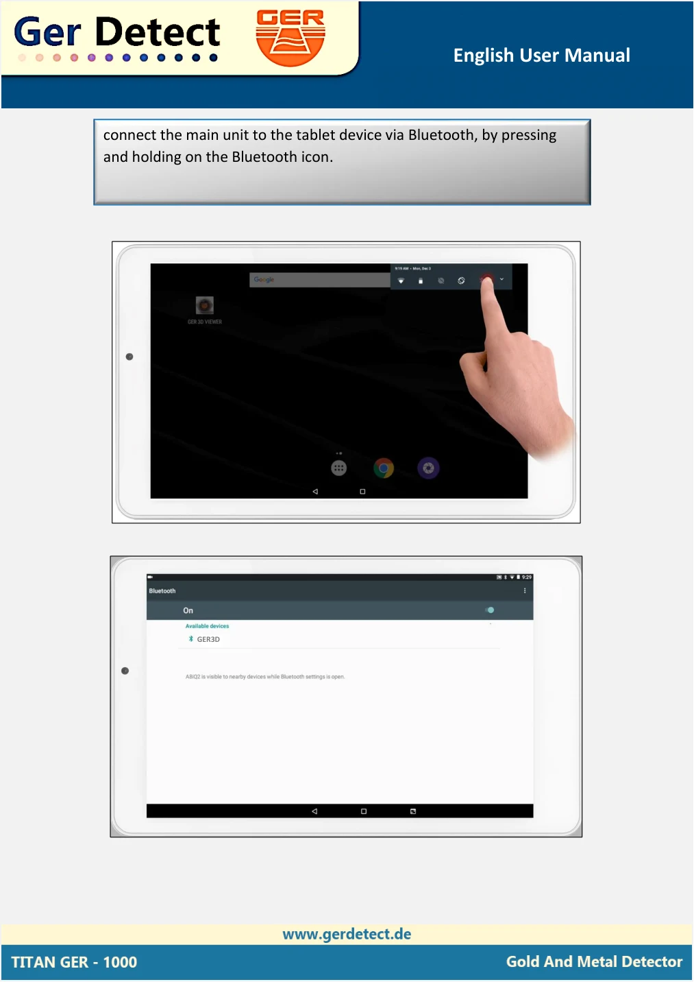
The documentation uses names including GER 3D Viewer, 3D GER Analyzer and GER3D. Follow the application supplied with your equipment; a different name or layout does not justify installing an unrelated program.
3D Scan Settings, Grid Spacing and Walking Patterns
In this Titan GER 1000 user guide, the scan grid is treated as a record of measurement positions. Correct line counts and consistent movement are essential to interpreting where a displayed feature appears.
| Setting | Manual instruction | Practical check |
|---|---|---|
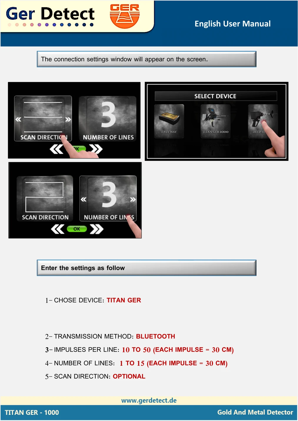
| Device | TITAN GER | Choose your detector, not another model in the application. |
| Transmission | Bluetooth | Complete pairing before connecting the scan. |
| Impulses per line | 10–50 | Plan the number of sampling positions before walking. |
| Spacing | 30 cm shown between sampling positions | Keep along-line and between-line spacing consistent with the illustrated grid. |
| Number of lines | 1–15 | Match the selected number to the lines actually recorded. |
| Direction | One direction or zigzag | Use the same walking pattern as the software selection. |
| Connection/start | Connect in the application; use the illustrated device Start control | Check that samples appear at the expected positions. |
One Direction or Zigzag: Keep the Pattern Consistent
One-direction scanning: record each line in the same direction and return to the starting side before the next line. Keep the non-recording return movement separate from the recorded line.
Zigzag scanning: record the first line in one direction, step to the next line, then record in the opposite direction. Continue alternating to match the selected pattern.
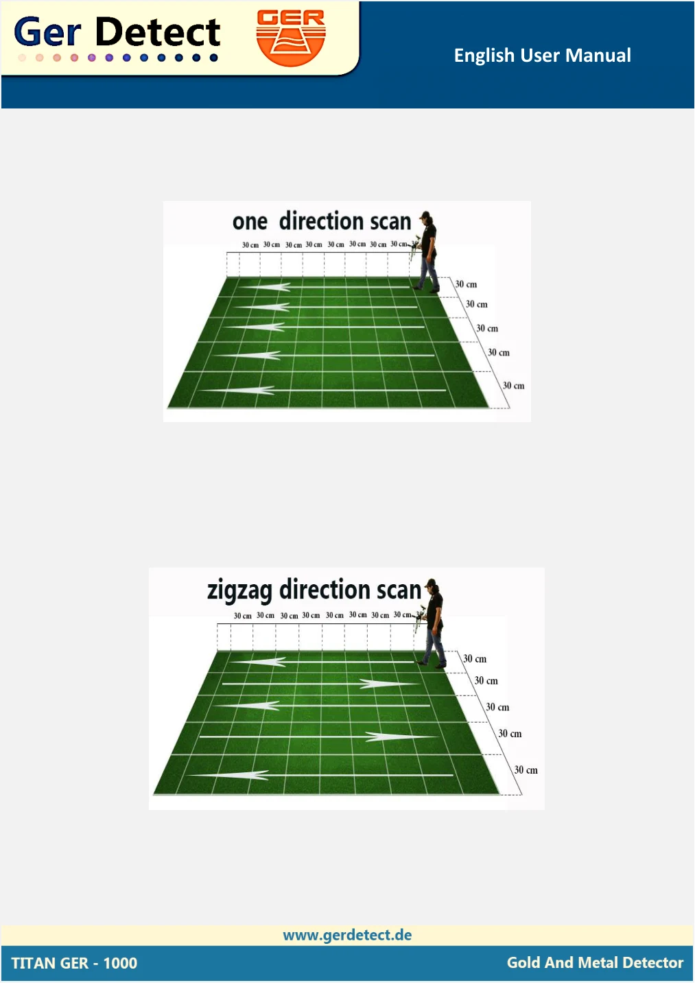
Worked Grid Example
Selecting 10 impulses and 5 lines gives 50 recorded positions. With points 30 cm apart, the distance from the first to the tenth point is 2.7 m, and from the first to the fifth line is 1.2 m. This point-to-point span differs from software that labels each sample as a complete 30 cm cell.
Measure and record your actual plot dimensions. Do not infer survey area from a range setting, and do not claim more depth because you selected more lines. Repeat a completed grid over the same marked area before expanding the survey.
Reading 3D Results, Depth Estimates and Saved Files
Start with the unedited scan. Check its line count, impulse count and orientation before using display adjustments. A stretched feature, a single isolated peak or an incomplete grid can reflect acquisition problems as well as an area worth rechecking.
| Software function | Useful action |
|---|---|
| Grid display | Match the selected area to recorded lines and impulses. |
| Cell navigation | Move between positions and record the selected-cell value. |
| Depth display | Record the estimate with its cell, grid and settings. |
| 2D/3D and view angles | Inspect the same dataset from different views. |
| Layer visibility | Review the software’s displayed categories without treating them as confirmed materials. |
| Reset view | Return to the original presentation after display adjustments. |
| Save project | Keep the editable GER file for later review. |
| Save image | Keep a static export alongside the project file. |
| Print report | Use the software’s report function with an available compatible printing setup. |
View the manual’s analyzer-control reference
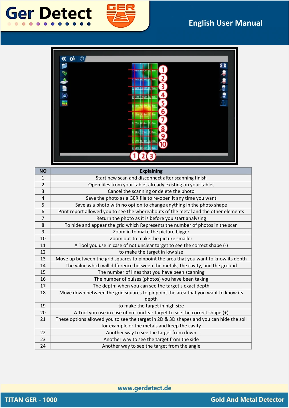
What Colours and Shapes Can Tell You
Use the legend and values in your software version. A colour alone cannot establish gold, gemstone content or an empty chamber. Likewise, changing the view angle or height scale does not create a new measurement or improve the underlying evidence.
Compare the location of a feature across repeat scans, including a grid recorded from a different direction. Keep acquisition settings documented so that a change in appearance can be traced to a changed setting, a changed scan path or a repeatable site response.
Save Both the Project and the Image
The manual distinguishes a GER project file from a static picture. Save the project before experimenting with analysis tools, then keep a separate image for sharing. A screenshot alone may not preserve the information needed for later review.
Printing distinction: the manual lists a software Print Report function. That does not establish that the Titan GER 1000 contains a built-in printer. Ask about a compatible printer before planning field printing.
Detection Depth and Range: 45 m, 12 m and 2500 m
The headline specification and system-specific instructions must be read separately. The table below identifies where the commonly quoted numbers come from, without turning them into a universal detection promise.
| Number | Source/context | How to use it |
|---|---|---|
| Up to 45 m | General manufacturer advertising and several manual system descriptions | A stated maximum; not a guaranteed depth for every target or system |
| Up to 12 m | English manual PI section, PDF page 32; Arabic PDF page 29 | A separate PI claim, not independently demonstrated in this guide |
| Up to 2500 m | Advertised front range and long-range menu setting | Horizontal range claim, not burial depth or mapped survey area |
| Displayed depth | Selected position in the analysis software | An estimate to record and investigate, not a measured excavation depth |
Target size, orientation, ground conditions, interference and setup affect responses. This guide does not establish a depth for a small nugget, a coin or a particular buried container. Ask for a documented test with the relevant target and measured burial depth if performance at a specific depth matters to your purchase.
A Practical Search and Verification Workflow
Use this workflow to apply the Titan GER 1000 user guide systematically. It is a suggested recording method from Detectors Shop, not a report of a completed field test.
- Define the question. Record whether you are investigating a metal response, a magnetic response or a possible subsurface anomaly.
- Inspect the surface. Note scrap, fences, services, vehicles and features that may influence the equipment.
- Fit the appropriate attachment. Complete calibration and record the baseline.
- Mark the candidate area. Use repeatable observations rather than one brief signal.
- Repeat with a controlled path. Keep settings comparable; for 3D work, record the exact grid and direction.
- Compare another relevant function. Record what it actually indicates. Do not count related outputs as independent proof.
- Keep the original data. Save project files, images, settings and site notes.
- Assess recovery separately. Confirm access permission and buried services; suspected underground voids require specialist assessment.
| Record | Include |
|---|---|
| Site and date | Plot reference, conditions, operator and nearby interference sources |
| Equipment | System, attachment/coil, battery state and relevant software version |
| Setup | Calibration, sensitivity, target selection and range where applicable |
| 3D grid | Impulses, lines, spacing, direction and marked starting corner |
| Observation | Signal location, repeat behaviour, screen values and estimated depth |
| Outcome | Unverified, rechecked or recovered; actual object and depth if confirmed |
Troubleshooting: Startup, Noise, Bluetooth and Scan Problems
| Symptom | Checks and next step |
|---|---|
| PI startup stops partway | Switch off, check the coil cable connection and battery, then restart with the coil connected as required by the manual. |
| Repeated battery alarm or shutdown | Stop and recharge. The manual advises against repeated restarts on a depleted battery. |
| Persistent background noise | Check carried metal, nearby interference and connectors; repeat the appropriate calibration and review sensitivity. |
| Ionic indication changes with heading | Review the manual’s orientation instructions and calibration before marking a target. |
| Magnetic response follows the operator | Check carried ferrous items and nearby equipment, then repeat with a consistent sensor position. |
| GER3D does not appear | Check detector power, Bluetooth activation and proximity. Restart pairing if necessary. |
| Bluetooth code rejected | Use the manual’s code 1000. Confirm that you selected GER3D; ask support if your version differs. |
| Paired tablet receives no scan data | Check TITAN GER selection, Bluetooth transmission, assigned COM port if required, application Connect and the device Start procedure. |
| Scan appears reversed or stretched | Compare the selected direction with actual walking, line counts, sample spacing and sensor movement. Repeat the original grid. |
| A feature disappears on repeat | Check the same coordinates, settings, calibration and scan path. Keep it unverified until the behaviour is understood. |
| Only a picture was saved | Look for the GER project file. For the next scan, save both the project and an image. |
| Print Report does not produce paper | Check for an installed compatible printer and tablet connection; a software button is not an integrated printer. |
For support, send the system name, a clear connector photograph, the screen message and your settings. For 3D issues, include the original GER file when possible, plus line count, impulses and walking pattern.
Battery Charging, Cleaning and Storage
- Use the original charger and follow the battery label and supplied instructions.
- Inspect leads before use and keep plugs free of dirt and moisture.
- Switch off before changing sensors or disconnecting power.
- Stop searching when the low-battery warning occurs and recharge before continuing.
- Clean external surfaces gently and dry the kit before packing it away.
- Keep the main electronics, tablet and battery dry. A coil rating does not waterproof the whole assembly.
- Store equipment in a dry place away from excessive heat; protect sensors and screen hinges during transport.
- Back up scan projects separately from the tablet before software maintenance.
The manufacturer’s environmental maxima are equipment ratings, not recommended storage targets. Follow the more restrictive instructions for the battery, charger and tablet where they differ.
Who Is Titan GER 1000 For? Price, Training and Warranty
The configuration suits users who want to learn several operating procedures and keep organised survey records. Beginners should allow time for attachment identification, calibration and scan-grid practice. Users focused on a single task may prefer a simpler setup.
For current availability and price, use the Titan GER 1000 product page. Ask Detectors Shop to confirm the supplied equipment version, tablet software and training arrangements before purchase.
Detectors Shop provides a five-year warranty, subject to its written terms. This is the retailer’s warranty. The supplied manufacturer manual states a two-year main-unit warranty with exclusions; the retailer’s five years should not be described as a five-year manufacturer warranty. Confirm covered components and service arrangements in writing.
Compare Equipment by Intended Use
If you are still comparing multi-system detectors, read the Titan X13 review and Titan 500 Smart field guide. Compare accessories, workflow and evidence for your intended target rather than choosing by headline depth alone.
Browse the Detectors Shop catalogue or contact our team for equipment selection and a delivery quotation for your destination.
Frequently Asked Questions About Titan GER 1000
What are the five Titan GER 1000 search systems?
Pulse induction, long range, ionic, magnetometer and 3D imaging. Cavity options and target categories are functions within the setup rather than additional main systems.
Does every system detect to 45 metres?
No. The general advertising quotes up to 45 m, while the supplied English manual separately advertises up to 12 m for pulse induction. Neither figure guarantees detection of a particular object.
What does the 2500 m setting mean?
It is a manufacturer-advertised front range and a long-range menu setting. It is not target burial depth or the dimensions of a recorded 3D grid.
What is the Bluetooth name and pairing code?
The supplied manual identifies GER3D and pairing code 1000. If a COM port is required, use the assigned port for your paired equipment.
How many impulses and lines can I select?
The documented scan settings allow 10–50 impulses per line and 1–15 lines. The illustrated grid uses 30 cm spacing. Match the software configuration to your actual scan path.
Why must I connect the PI coil before startup?
The manual warns that PI startup can stop if the coil cable is not connected. Assemble and connect the selected system before switching on.
How high should the PI coil be above the ground?
The supplied manual specifies approximately 5–10 cm during steady left-to-right sweeping. Keep movement consistent and recalibrate if necessary.
Does a non-ferrous response mean gold?
No. Many materials are non-ferrous, including copper, aluminium, silver and gold. The response helps assess a target but does not confirm its composition.
Can the magnetometer identify gold directly?
A magnetic indication alone does not identify gold. The manufacturer describes this function for magnetic metals such as iron; investigate repeatable responses without assuming value or material.
Does a 3D scan show a photograph of underground objects?
No. It is a processed visual representation of recorded measurements. Shapes, colours and depth estimates require careful interpretation and repeat checks.
Does selecting diamonds or gemstones confirm their presence?
No. These are manufacturer-provided search categories. Selecting a category or receiving an indication does not establish gemstone identity or commercial value.
Is Titan GER 1000 waterproof?
The main detector is not waterproof. The manufacturer separately lists a coil rating to 30 cm. Keep the electronics and connections dry and follow the manual’s restrictions on rain and very wet ground.
Should I save a GER file or an image?
Save both when available. The GER project supports later review, while an image is a static output useful for sharing. Keep the original project before changing analysis settings.
Does Print Report mean the device has a built-in printer?
No. The manual describes a software printing function. Confirm a compatible printer and tablet setup separately.
What warranty does Detectors Shop provide?
Detectors Shop provides a five-year retailer warranty, subject to its written terms. Confirm coverage and service arrangements before purchase.
Where can I get the manual or help with setup?
Use the manual links below and contact Detectors Shop through the official contact page or WhatsApp. Keep this Titan GER 1000 user guide available when checking connections and scan settings.
Detectors Shop: Dubai Showroom, Support and Social Channels
For setup help, equipment availability and training enquiries, contact Detectors Shop. Tell the team which system you are using and include your settings or screen photographs.
Dubai showroomTechnic Building, third floor, Office 301
Salah Al Din Street, Al Muteena, Deira
Dubai, United Arab Emirates
- WhatsApp: +971 56 168 8466
- Sales phone: +971 54 367 7699
- Dubai landline: +971 4 320 8988
- Email: [email protected]
- Location and enquiries: official contact page and location map
For collection or service at another branch, ask the team to confirm the current address and arrangements before travelling.
Follow our official channels: YouTube · Facebook · Instagram · TikTok.
Watch a short Titan GER 1000 presentation
Manual Downloads and Source Notes
- Download the Titan GER 1000 English user manual (PDF).
- Download the Arabic user manual (PDF).
- UIG Detectors: manufacturer specifications and accessories.
- GER Detect: Titan GER 1000 product reference.
Operating illustrations are extracted from the English manual supplied for this guide and retain manufacturer attribution. Public download editions may differ from supplied copies. The scan example and field log are editorial guidance from Detectors Shop. The package confirmation and five-year retailer warranty were supplied by Detectors Shop.
This guide does not claim a verified find, measured detection depth or laboratory validation from the supplied photographs and videos. Menu categories and advertised maxima are identified as such so readers can distinguish them from confirmed field outcomes.
Ready to choose your setup or need help with the first scan?
View Titan GER 1000 at Detectors Shop or ask our team on WhatsApp.
